3D scanning and printing
Week 5
3D scanning and printing
Tasks
Group assignment:
group project: test the design rules for your printer(s)
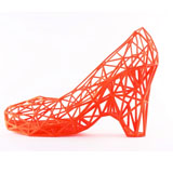
design and 3D print an object (small, few cm) that could not be made subtractively
3D scan an object (and optionally print it) (extra credit: make your own scanner)
Group assignment. printing test
For our group assignment we decided to model a print test for each of our 3d printers at the lab, a prusa i3, a BQ witbox, a zmorph and a Stratasys Fortus 250mc. I started to model the test in Illustrator and then exported to Japanese AI, that’s the format 3d Studio Max recognizes, and in Studio MAX imported the file, following these steps:

Menu-->Import-->Select AI file, select desired option
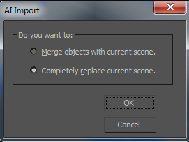
Menu-->Import-->Select AI file, select desired option
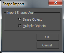
Imported vector file in spline mode
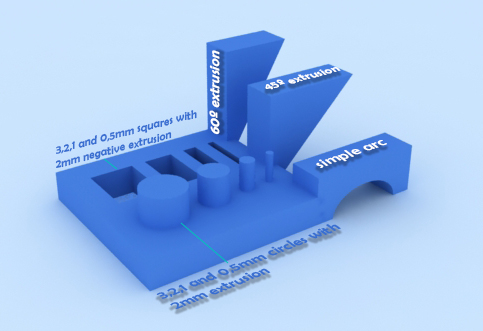
I converted the splines to editable poly and started making extrusions and aligning the polygons. This is the final result and the scheme for printing
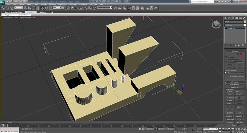
Scheme of the model, a render edited in photoshop by adding some text
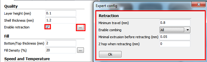
I started to print in HD definition and it didn't get so well. i Had to change the retraction settings to get better results, wich i did
Retraction settings changed
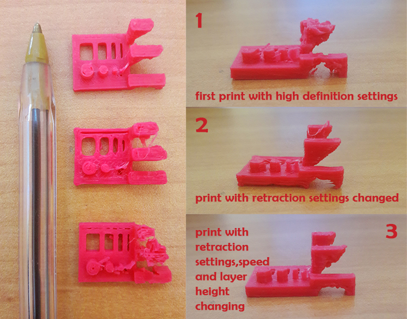
As you can see ths results show the improvement of the printings. I changed also the layer height to 0.1mm and reduced print speed to 35mm/seg.
Final result
Vector file
3d MAX file
STL file
References - Calibration Models in thingiverse,
3D printing
After searching something to do, i've came to a conclusion that there are a few models that i would like to test. I decided to model 3 pieces with diferent technics:
FILES
An oiltank coin jail
For this purpose i want to print something that is opened, so i can see inside, and put an object inside it.
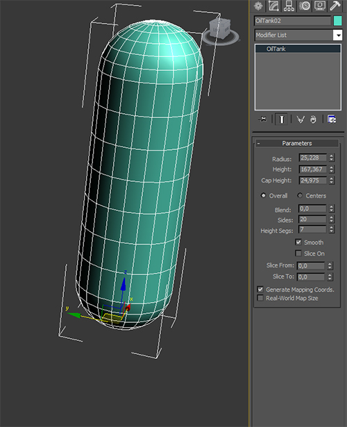
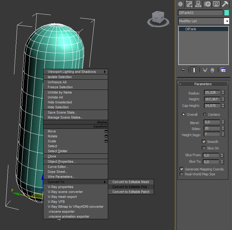
In 3d Studio Max, i selected extended primitives-->oiltank with this parameters:
Parameters of the oiltank
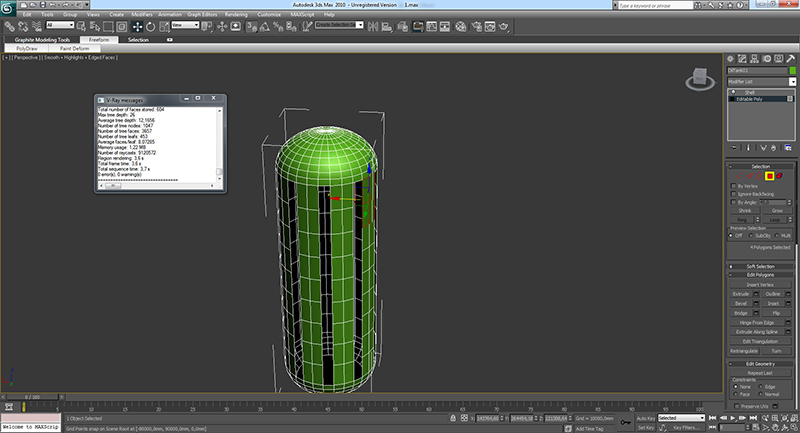
Converting to editable poly
Editing and deleting the polygons
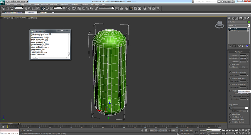
Applying a 1mm shell modifier
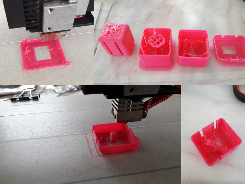
The idea is to 3d print, pause the printing and insert a coin inside the model and finish the model.
3d printing process
A Chamfer box with 3d print inside
For this model i wanted to print 2 objects, a box with a hedra inside with support structurethat i could cut at the end.
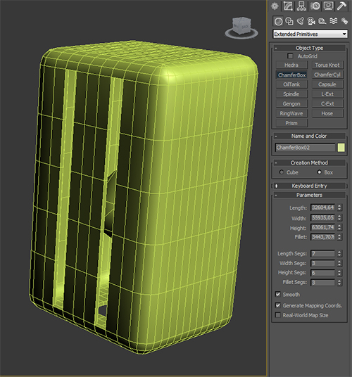
Parameters of the chamferbox (extended primitives-->chamferbox)
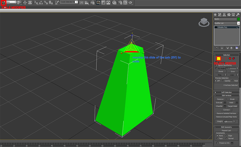
Adding support structure, a simple box scaling the top to be thinner than the base. I selected the vertex, the scale tool and reduced the top
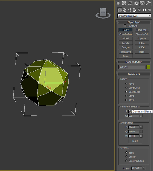
Creating a Hedra-dodec to put in the top of the support structure
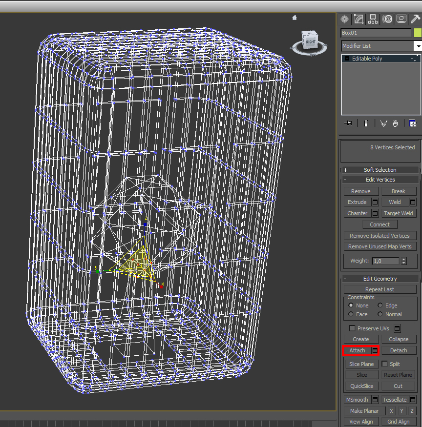
Aligning all the objects and attaching them all, to form one single object and export to STL.
The 3d printing didn't went so well, first the support for the dodec wasn't at ground zero.the model was too small and the dodec support started to crash, i had to change the model and make a stronger base for the support and made a brim for the platform adhesion type unde CURA.
bad 3d printed models, diferent z for the pieces, and filament jam.
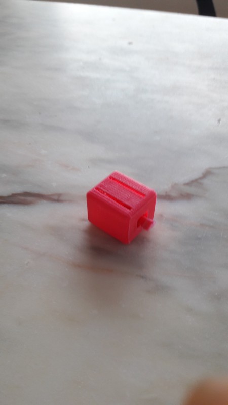
After optimizing i got a better result. final result of the 3dprint.
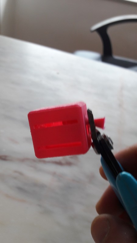
i had to cut the support with a plier
Aftercut
Chamferbox with an interior slide
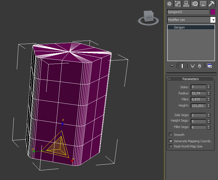
This object is impossible to make subtratively. i started to draw a gengon (extended primitives-->gengon). Gengon parameters
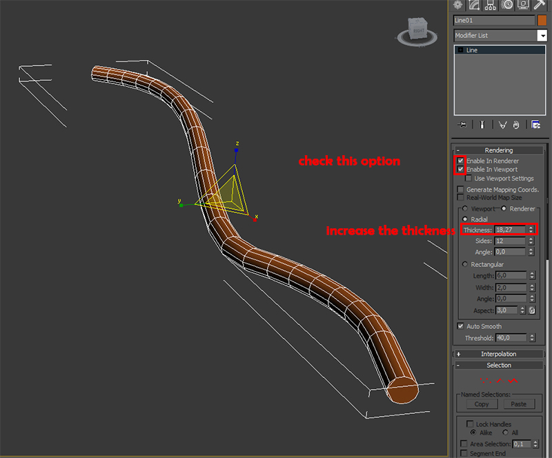
spline modelling. Ensure to transform it in editable poly in the end.
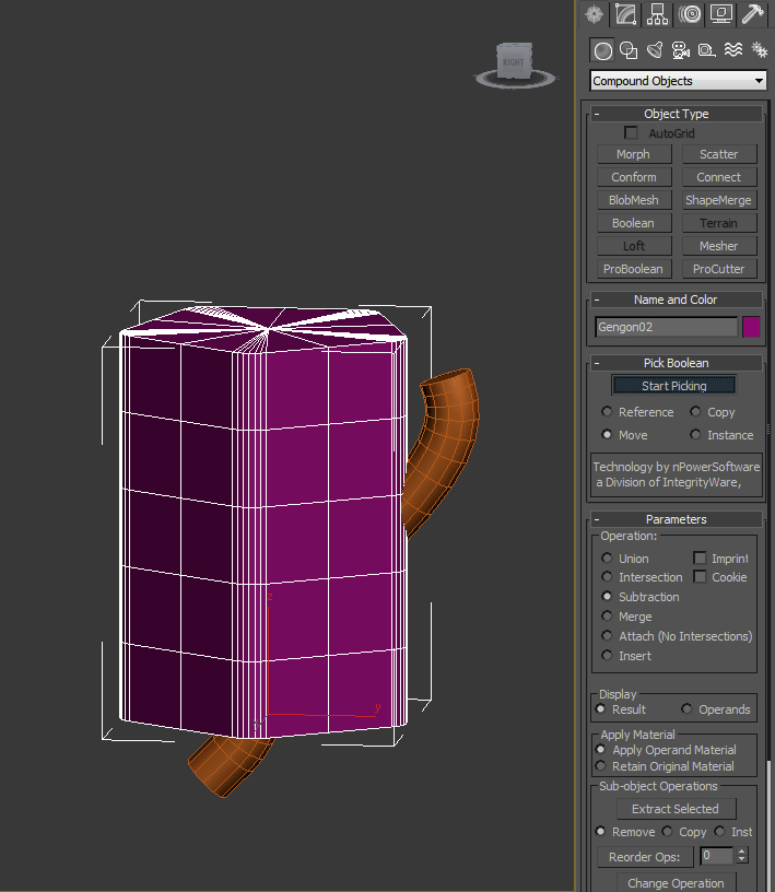
Pro boolean operation. Just select the other object and let 3d max do the rest.
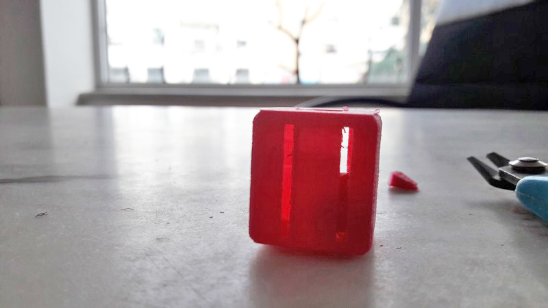
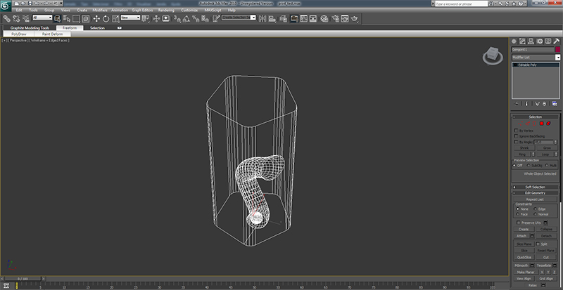
Final result
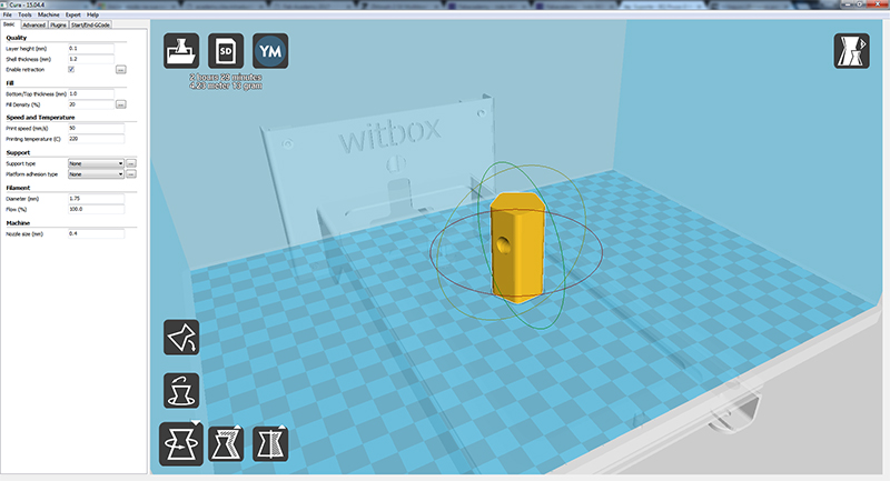
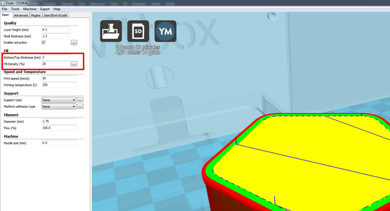
Slicing the 3d Model with CURA.
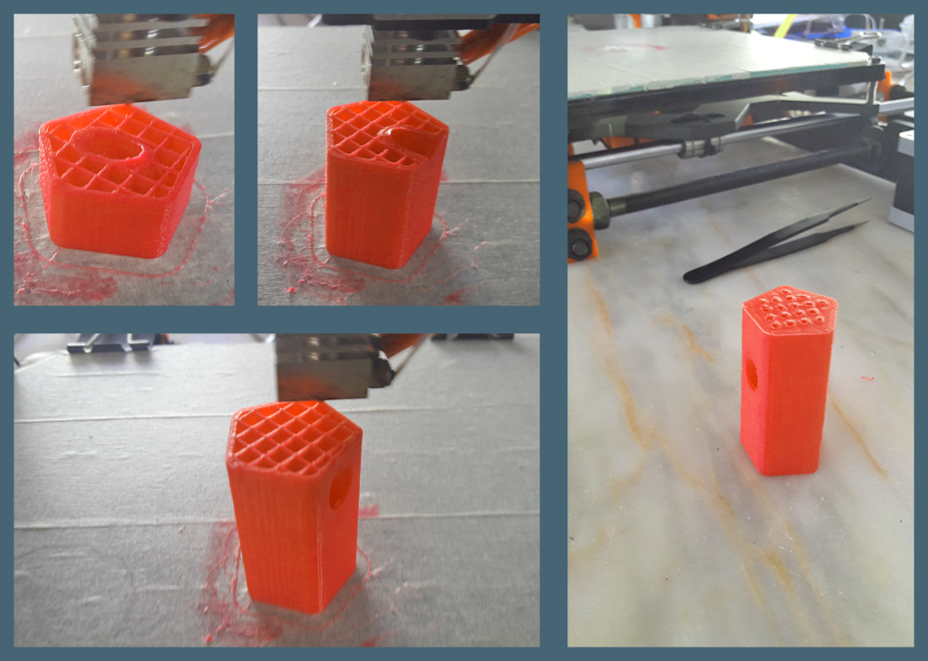
The final result didn't work so well at the top, so next time i'll change the parameters of the infill, or the top thickness or the infill %.
Result of the 3D Print.
3D Studio MAX files
STL Files
Cura Printing Profile
3D Scanning
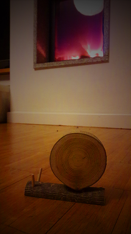
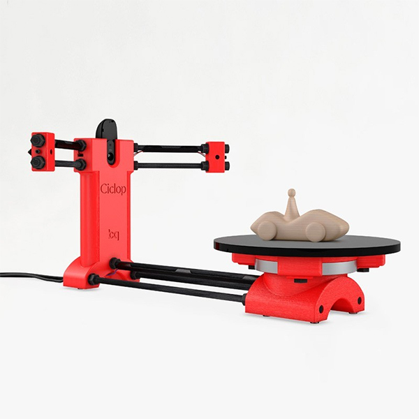
For this assignment i used the Ciclop Scanner. It works with two laser beams and one webcam. The first thing to do was to find an object to scan. I found a wood snail done by my friend Nuno Alves, also a student from Fabacademy.
My object to 3d Scan.
After that i started to install ciclop software in my laptop, under windows OS.
BQ ciclop 3D scanner
I Installed Logitech camera drivers drivers from here and
Horus installer from here
After installing these software and drivers i started Horus, and skipped the easy interface. It was time to calibrate all the components and adjusting the image quality.
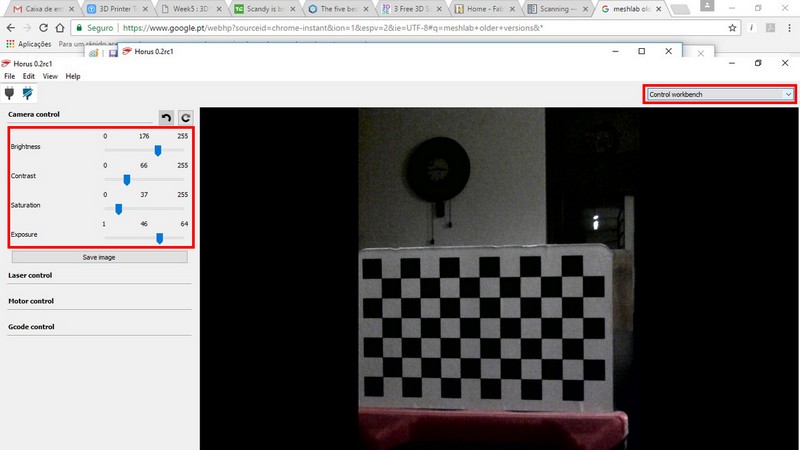
I adjusted the camera settings acording to the light of my room in the control workbench
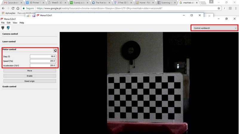
Then i tested the motor in the same workbench and all went fine
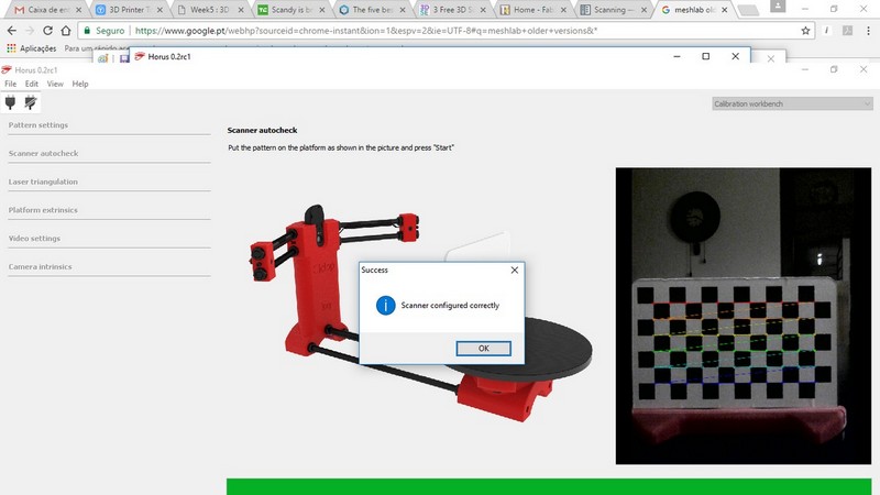
Then i passed to calibration workbench.
Made a scanner autocheck
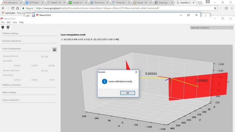
Made a laser triangulation
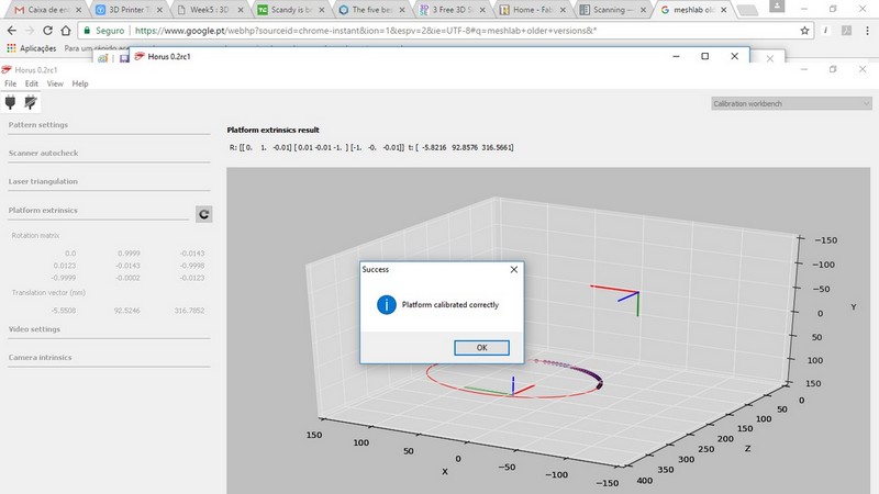
Tested the platform extrinsics
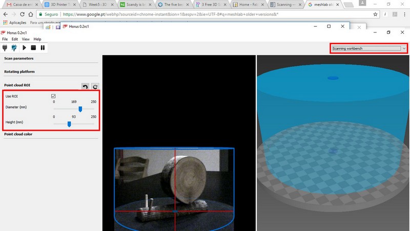
Pass to scanning process, by clicking Scanning workbench
I changed the values of Point cloud ROI (region of interest) to reduce my scaning area and speed the scaning process
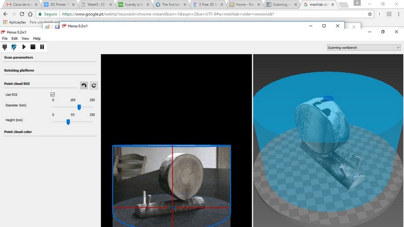
And clicked the play button to start the process. It took about 15min to scan the snail. I got good results.
Scaning process was finished. I save the file and passed to meshlab. I had to download an older version to follow the tutorial i found here
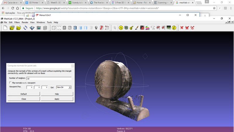
I imported the point file created in Horus and start the filtering process. Meshlab has lots of complex operations and i'm keen to test them someday.
Filters -> Normals, Curvatures and Orientation -> Compute Normals for Point Sets
Filters -> Remeshing, Simplification and Reconstruction -> Surface Reconstruction: Poisson
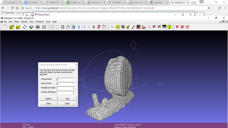
Exported the file to STL and voila!
References - Horus Documentation online,
Snail point cloud file
Snail STL File
Meshlabs project