#06. Electronics Design
Redesigning Echo Hello-World
This week we had to add a LED and a button to a well knowned board named Echo Hello-World. But, because is always good to have more work them the one we were asked to do, i decided i should use not one but three LEDs. This way, my board wouldn't just blink, it would glow.
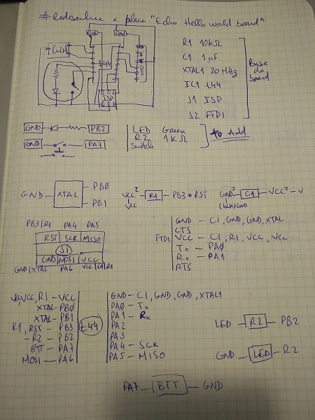
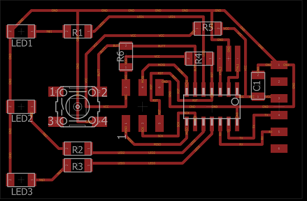
Started with understanding the board, and how it would work, what did what, what goes where, etc etc (picture above). Getting sure that the routes where correct was the first thing, and since there were a coupple of free pins on the Attiny45 i wanted to use them to add some extra LEDs. The components to add were 3x100ohm resistors for 3xGreen LEDs and a 10kohm resistor for the button. Below you can check the full list of components i used:
- R1 100ohm
- R2 100ohm
- R3 100ohm
- R4 10kohm
- R5 0ohm
- R6 10kohm
- C1 1uF
- LEDs Green
- Button
- Resonator 20Mhz
- Attiny44
- ISP
- FTDI
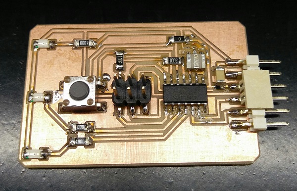
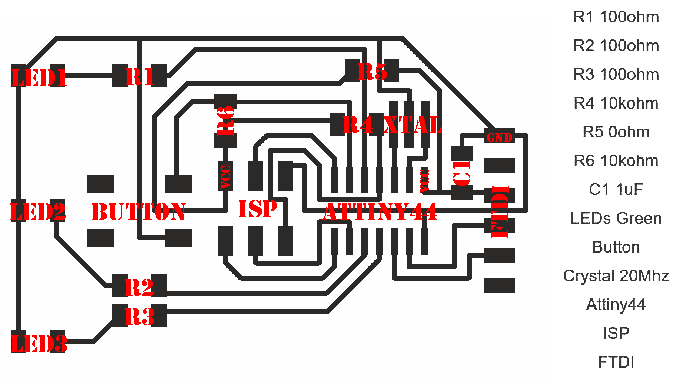
As seen in the image above i used the method of linking the components by the use of small links with tags, this way there isn't a mess of wires going all around. The main difference you may see is the 3 LEDs and a 0ohm resistor that will be used as a bridge without wish i wasn't able to make all the routes. After i switch to the board mode, it took some time (almost a day considering that i had to redo everything once due to a simple mistake) to get everything to work out correctly and all routes got to the right place, at the end i only had to space out some resistor pads since there wasn't enought clearance between. Here's the end result:
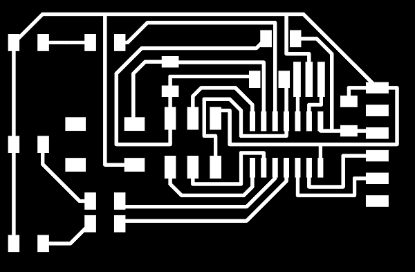
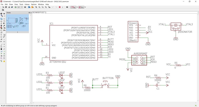
Finally used the Carvey with the Easel app and carved the board away, this time did only the outlines of the path to tryout and workout really good, clean look, a fraction of machining time as well as less stress on the tool. Soldering came afterwards and all went well with just some dificulty of the resonator. Below there's an image of the completed board and the schematic i made to help me put all together.